Comprehensive Guide to Operating and Maintaining Winding Machines
In order to give full play to the best performance of the equipment and ensure the safety of the operator, please read this operation manual in detail, when you find any difficult problems in use and this manual can not provide answers, please contact the company, our professionals will provide you with satisfactory service in the fastest time.
10/18/202535 min read
Slider type toroidal winding machine operation guide


Step 1 Adjust the coil tightness
Step 2 Adjust pressure of the clamping plate

Step 3 Place the core through the cable magazine


Step 6 Adjust the winding density
Step 5 Set the parameters of the controller
Step 4 Align the inner diameter center of the core with the outlet position of the wire spreader


Step 9 Take down the final product
Step 8 Start winding
Step 7 Storage wire
Gear type toroidal winding machine operation guide


Step 1 Adjusting the brake resistance
Step 4 Adjust iron core position
Step 3 Restore the wire storage ring and gear
Step 2 Place the iron core
Step 6 Start winding
Step 5 wire storage

Step 7 Remove iron core
Chapter 2 Describes the functions of the operation panel, interfaces, and buttons
The company set a large number of winding machine industry engineering and technical personnel after years of research and development and production experience, developed a new generation of series winding equipment, widely used in the ring transformer, transformer, voltage regulator, inductor coil, ring core, EI transformer and other manufacturing industries, products by the majority of users proved to have the following advantages:
1.The new type gear type medium speed winding machine adopts the main transmission gear toroidal without notch, which has the advantages of low running noise, long service life, easy operation and low maintenance cost. And the winding speed is stable, and it is not easy to break the line when winding small wire diameter products.
2.Tape wrapping machine adopts the latest design of transmission gear and magazine, the product has small inner diameter, faster tape wrapping speed and low maintenance cost.
3.Fuselage and main components are all high-temperature paint or electroplating process, not easy to rust and oxidation.
4.The rubber wheel is made of solid metal material and high toughness plastic injection molding, which is more durable than the traditional pure plastic inner core, and the tray can be replaced separately. Extended service life.
5.The pulley is made of high quality metal materials, with high concentricity and less vibration and noise.
6.Equipment circuit adopts the latest intelligent control mode, each function switch only needs two to three lines, equipment maintenance, simple maintenance.
7.The use of internationally renowned brand inverter and induction motor, stable work, energy saving and consumption reduction, energy saving 30% than the traditional way, the use of equipment cost is lower.
8.The product specifications that can be saved are increased to 50, which is displayed on a full-Chinese LCD screen. The setting of winding data is simple and intuitive, and the practical functions such as automatic operation, multi-segment line density setting, and output statistics are added.
9.The controller can adapt to the voltage range of 200-250V, and can also ensure accurate control in the unstable state of the power supply environment, without turning errors; The preset number of turns and the completed number of turns can be displayed at the same time. It has the function of remembering the number of turns wound by power failure, which can prevent the number of turns wound by accidental shutdown from being cleared.
10.Tape machine intelligent operation function, more simple and efficient operation.
Adhering to the business philosophy of "better products and convenient customer service", the company constantly strengthens the level of technology research and development and after-sales service, as well as product upgrading and improvement, to provide maximum protection for the normal use of the majority of users.
In order to give full play to the best performance of the equipment and ensure the safety of the operator, please read this operation manual in detail, when you find any difficult problems in use and this manual can not provide answers, please contact the company, our professionals will provide you with satisfactory service in the fastest time.
Chapter 1 Safety Precautions
1. Before powering on, please check whether the power supply conforms to the rated value of the equipment (220V/50Hz), and the power of the power line. The power line of each equipment is required to be at least 1.5mm2 copper wire. Ensure that the equipment will not work unstable or overheat the power line due to insufficient line power.
2. Check whether the magazine and gear ring are properly installed and locked.
3. Check whether foreign objects are found on the operating platform of the device in the range of any rotating parts.
4. Before pressing the start/stop switch to start winding the product, please make sure that all matters have been prepared, such as whether the wire is hung tightly during the storage operation, whether the wire is pulled in the correct position during the winding operation, and whether the step and process of the controller to be run are correct.
5. During the operation of the equipment, do not place your hand close to the mechanical operation to avoid accidents.
6. In case of disconnection or mechanical failure during operation, press the start/stop switch or power switch on the device operation panel immediately.
7. Please do not leave while the equipment is in operation.
8. In order to ensure that the number of turns is accurate, often check whether the number of turns sensor is in the best induction range.
9. When moving the equipment, ensure that the handling tools or personnel can bear the corresponding weight to avoid accidents.
10. Properly connect the ground cable before using the device. Otherwise, there may be high static electricity on the device shell.
11. When not used for a long time, the metal parts and gear parts of the equipment should be filled with anti-rust oil, and do a good job of moisture and dust protection.
2.1 Functions of machine operation panel

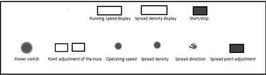
The power switch---- turns on the power supply clockwise and turns off the power supply when pressing down.
Spread head adjustment----- Manually adjust the stop position of the head tooth ring or cable magazine/tape ring.
Running speed----- Set the maximum running speed of the machine head. Wire spacing----- When winding the product, set the spacing of each turn of the winding (the wire spacing of the coil on the core/magnetic ring).
Wire routing direction----- Sets the wire routing direction for manual wire routing and the movement direction of the core/magnetic ring when moving.
Click cabling adjustment----- Manually adjust the position of the iron core or magnetic ring on the cabling device.
Start/stop----- To start and stop the wire winding/tape wrapping, press once to start. Press again to stop.
Running speed display----- Displays the current storage/winding speed value.
Line density display----- Displays the rotational speed of the current line spacing.
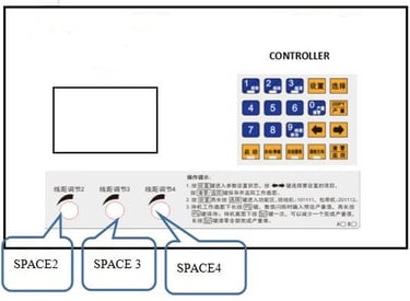
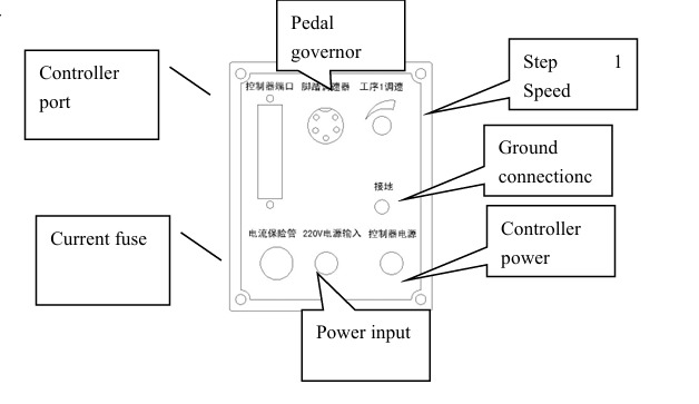
2.2 Functions and Usage of the controller Operation panel
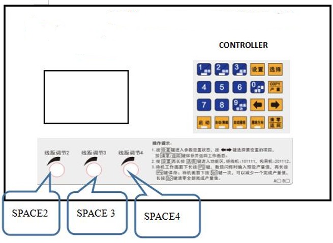
Key function instructions:
1. Set Enter the data editing state, press the setting key repeatedly to jump directly to the next setting page, (the operation is invalid in the running state)
2. Select Select the step to run in standby. (Operation invalid in running state)
3. Automatic wiring with indicator light, when the light is on, the core steering is automatically controlled (the direction of the core wiring rotation is determined by article 6 below when the step is started for the first time), when the light is not on, the direction of the wiring is controlled by the toggles switch on the panel (the operation is effective in the step setting page, each step can set the automatic wiring or manual wiring direction separately).
4. Wireing direction With an indicator, the operation is effective in the setting state. When the iron core rotates clockwise when it is on, it starts counterclockwise when it is off. The operation iseffective when each step is set on the page (the operation is effective when each step is set on the page).
5.Start/stop It has an indicator. When it is on, it is in the running state. When it is off, it is in the standby state. (Set the value 7 input function in the state)
6. Automatic/pedal with indicator light, when it is on, it will run directly after pressing the start key, when it is not on, it will run with the external pedal speed regulation, (the setting state is the value 8 input function)
7. Wire pitch modification In the suspended state after running, operate once, the number of completed laps flashes, press the arrow key to add or subtract the number of completed laps displayed; Press the turn number change key again to save and exit. (Set the value 9 input function in the state)
8. Output clearance In the standby state, the output is reduced by 1 per press. Press and hold for 2 seconds to clear the finished output. (The operation is invalid in the Settings state)
9.Left and right arrow In the setting state, select the item to be edited, and press the key for each parameter set (that is, press the key for setting the state and save the setting function at the same time); Save the preset parameters and automatically skip to the next parameter to be set, press Key returns to the previous parameter value; In the standby state, use the turn number change key to set the turn number addition or subtraction function.
10.COPY/output In the setting state, it is the COPY function. Press the copy key to copy all parameter Settings of the previous step. In the standby state, it is the output function key, press the output key for 2 seconds, the output value flashes, then press the number key to enter the output value, and then long press the output key for 2 seconds to save (operation is invalid in the running and setting state), tap once to convert the output setting value displayed in the standby state, and automatically change back to the completed output value after release.
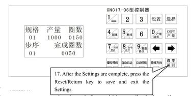
11. Clear/save in the standby and running state, touch once to clear the completed circle value; In the setting data state, save parameters and return to the standby state function key, return to the standby state of Step 01 page.
12. Digit key 0-9 Enter the parameter value to be preset in the Setting state. In the standby or running state, the function key is the function key explained above.
13. Wire Spacing adjustment 2----- If the multi-segment cable distance is used, adjust the cable distance to step distance 2.
14.Wire Spacing adjustment 3----- If the multi-segment cable distance is used, adjust the cable distance to step distance 3.
15. Wire Spacing adjustment 4----- If the multi-segment cable distance is used, adjust the cable distance to step distance 4.
2.3 Controller and External ports
Controller rear panel
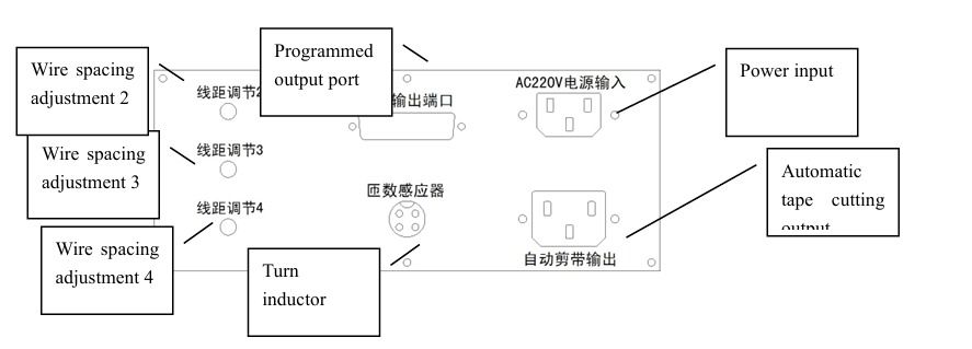
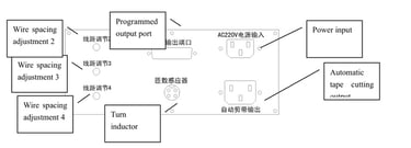
Ports on the rear panel of the controller
The programmed output port----- is connected to the controller port on the rear panel of the machine.
Automatic clipper output----- Connect to the power plug of the automatic clipper or brake of the tape wrapping machine.
Turn sensor----- turn sensor connected to the head.
Machine back panel
Machine rear panel interface
Controller port----- Connects to the controller programmed output port.
Foot governor-----5 pin aviation socket, connected to foot governor.
Controller power supply----- Connects to the power input port on the controller.
Speed regulation in step 1----- Adjust the speed set to the maximum running speed of the step (storage line/tape) in step 1.
Current fuse----- Install fuse (15A).
Chapter 3 Equipment functions and operation instructions
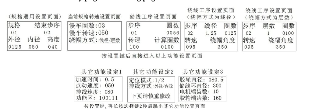
3.1 Controller Standby and Setting Page
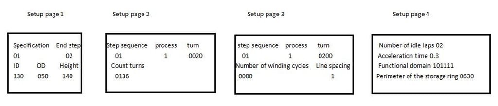
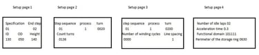
3.2 Parameter Setting range and function definition
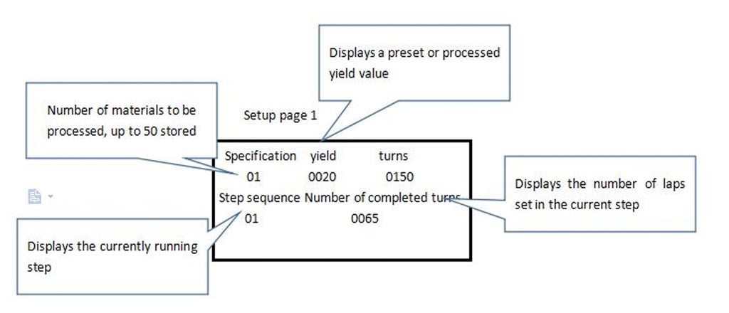
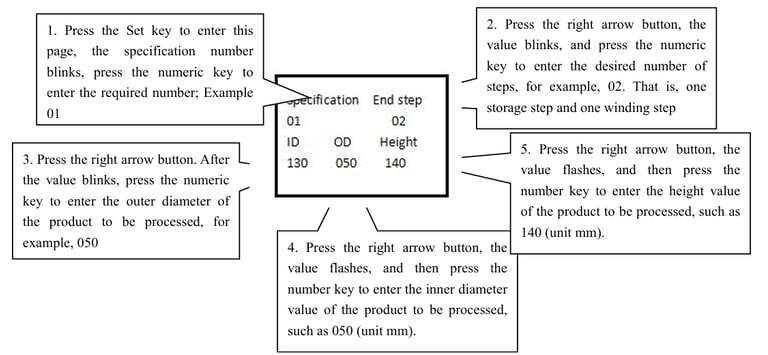
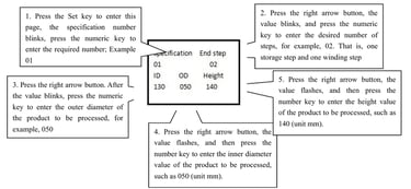
1. Specifications: 01-50 (50 product specifications can be set separately).
2. End step: 01-20 Set the total number of boot steps that need to be started. For example, if the storage line is wound once, set 02 and if the storage line is wound twice, set 03.
3. Outer diameter and inner diameter, height 000-999 setting value is used for the system to automatically calculate the number of stored coils. There is no other actual control function, and the calculated value can be entered arbitrarily without reference to the system.
4. Step: 01-20 This item cannot be set, and the step number of the current page is displayed (a maximum of 20 startup step parameters can be set/saved under each specification).
5. Procedure: 1-2 Set to 1 means that the step is the storage function, set to 2 means that the step is the winding function.
6. Numberof turns: 0000-9999 Sets the preset number of turns for the current step.
7. Calculation of the number of turns: this project is the automatic calculation and display project of the system, which cannot be set. For example, when the iron core size is correctly entered on the specification setting page, and then the number of winding turns of step 02 is set first, and then return to the step 01 setting page, the system will automatically calculate the approximate value of the storage coil, and the user can input the value of this turn into the storage coil number setting project; The calculation result of this function will have a certain error, it is recommended to add a certain number of turns according to the calculation result.
8. Numberof winding cycles 0000-9999: Set the number of cycles when the core turns to automatic reversal in automatic wiring mode. (After setting the value, it also needs to be used in accordance with the automatic wiring function on the keyboard)
9. Line Distance 1-4: Set the line distance adjustment mode used when the current step is started. If it is set to 1, adjust the line distance knob on the panel of the machine, and if it is set to 2/3/4, adjust the corresponding knob behind the controller. Note: The step set to line distance 1 must be the starting step with the fewest turns of all the winding, i.e. the winding with the fastest wiring speed.
10. Output: 0000-9999 displays the number of products that have been processed. When the preset output is started, the buzzer alarms and prohibits the start; When the output is set to 0000, the output is not restricted.
11. Number of completed turns: 0000-9999 Displays the number of laps that have been started in the current step.
12. Acceleration time: 0.1-9.9 Set the start time head running acceleration time; . 0-5 seconds, usually set to 0.5-1.0 (This function requires the function area set to 101211 to be effective).
13. Number of laps: 00-20 Set the automatic start state, when winding to the last number of laps, the automatic deceleration of the equipment has reduced the problem of incorrect number of completed laps caused by mechanical inertia.
14. Girth of magazine: 0000-9999 Set the girth value of the wire magazine of this model. This parameter is used to calculate the number of coils.
15. Ribbon: 1-6 represents the order displayed on the screen, and all specifications perform a ribbon setting value. 1. Spindle operation mode: the winding machine is set to 1 or 3 tape wrapping machine is set to 2/ or 4 The winding machine is usually set to 100111, and the wrapping machine is usually set to 200112
3.3 Operation method of wire storage (tape storage) process and wire winding (tape wrapping) process
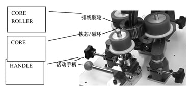
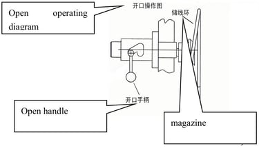
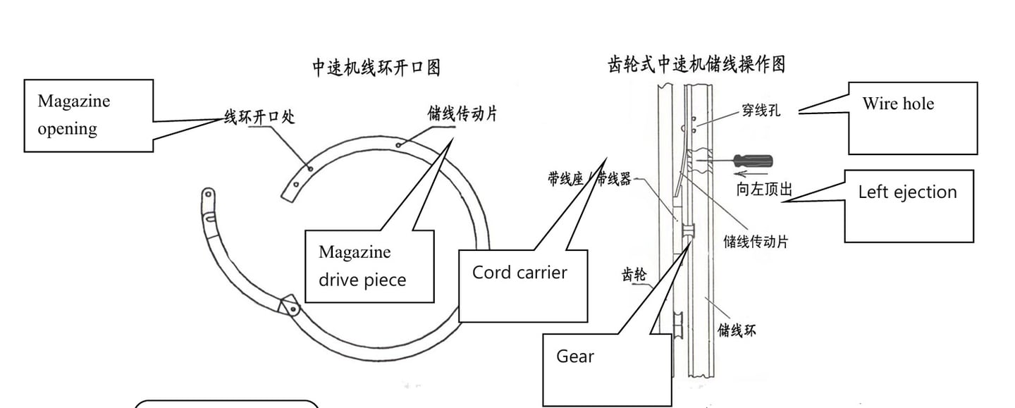
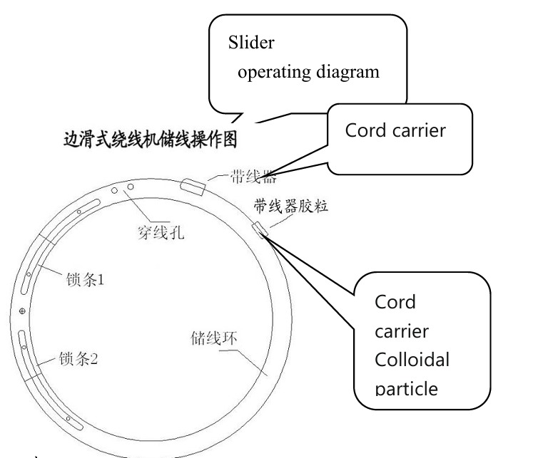
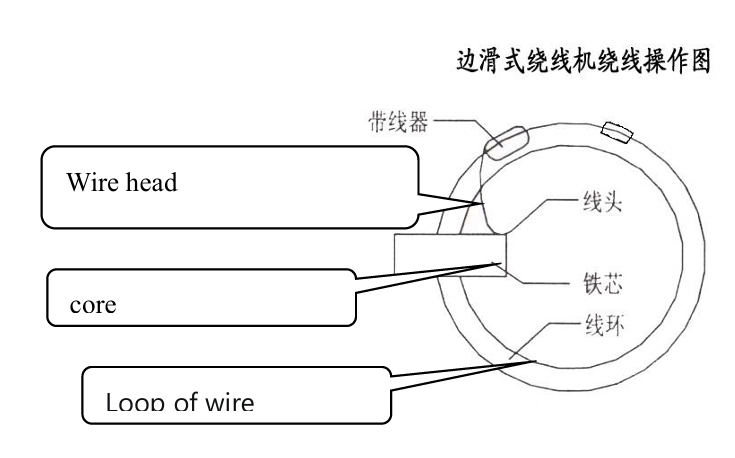
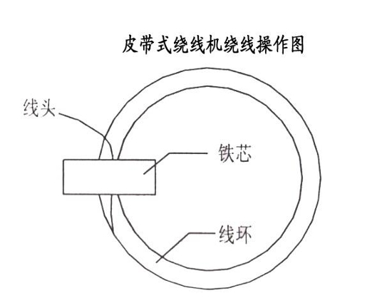
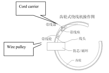
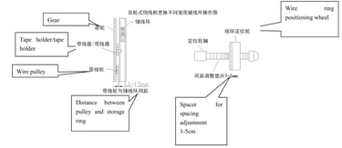
1. For different types of models, open the opening of the cable magazine/tape ring by referring to the figure below. Put the iron core/magnetic ring through the cable magazine and place it between the three cable rubber wheels.
2. Adjust the positions of the three rubber wheels on the wire spreader to clamp them according to the size of the iron core or magnetic ring, and align the inner diameter center of the iron core or magnetic ring with the outlet position of the wire spreader or wire reel.

3. When storing the wire, press the select button on the controller, select step 01 or other step set as step 1, then pull out the cable head from the cable support to fix the wire ring threading hole, press the start/stop switch on the machine panel, slowly step down the pedal governor (if you choose automatic operation, you do not need to use the governor), and start storing the wire.
4. The magazine of the medium speed winding machine usually has 2 groups of threading holes, 1 group at the bottom and 1 group on the right side of the right side, usually the wire head is fixed on the threading hole on the right side of the online ring when the wire diameter is small, and the large wire diameter is fixed on the bottom threading hole.
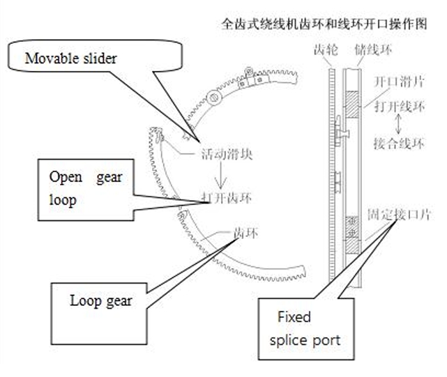
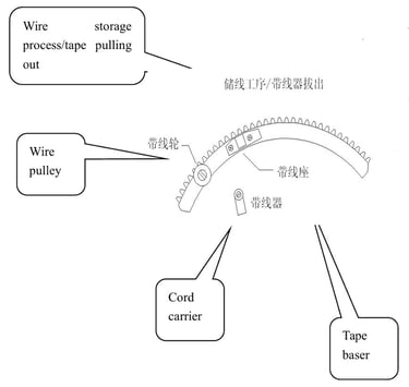
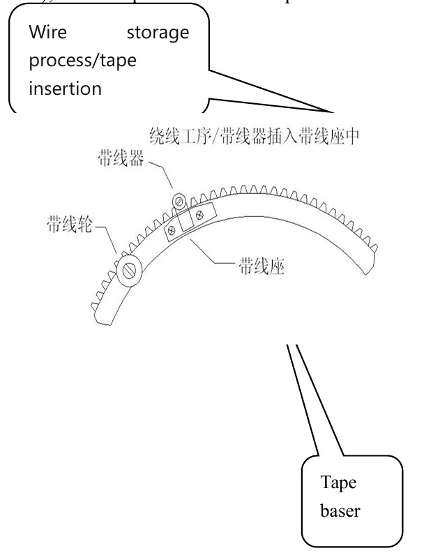
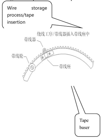
5. The gear type medium speed winding machine pulls out the pin-type cable belt before the storage operation, and plugs it back into the cable base after the storage is completed; For details, see section 4.10 below.
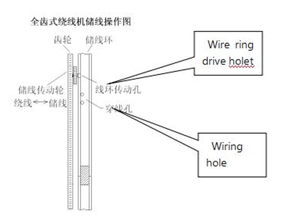
6. When the full-gear winding machine is storing the wire, the drive wheel of the wire storage line is stuck on the drive hole of the wire ring counterclockwise, and it should be noted that it only needs to be just touched and cannot be tightened forcefully; After the storage line is completed, return the gear direction and tighten it.
7. When two or more wires are needed and wound, just fix two or more wires directly on the threading hole, other operations are the same.
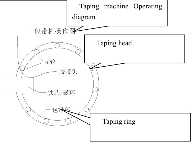
8. When the tape wrapping machine is storing the tape (that is, before the number of tape magazines is not completed and the tape is not cut), it needs to run at low speed first, otherwise it is easy to have the problem of tape stretching and broken tape; The equipment has the function of automatic storage belt low speed operation, which can adjust the procedure 1 speed regulating potentiometer on the back panel of the chassis to set the storage speed.
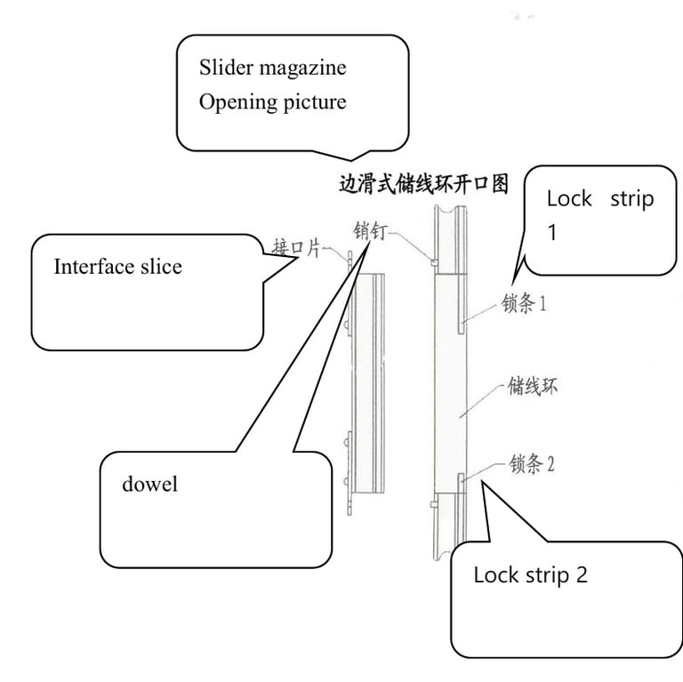
9. The magazine opening method and storage line operation method diagram of various models:
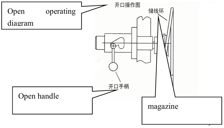


10.After wire storage/tape storage is completed, cut the wire head/tape head (gear type winding machine should loosen the handle of the wire ring pressure before cutting the wire head), then hold the wire head/tape head on the side of the wire magazine with your hand, put it on the wire carrier/tape wheel according to the following figure for different models, press the start/stop switch, and start winding/tape wrapping. Note that the thread/glue lead must be released after 3-5 turns of winding, and pay attention to the swing of the thread during the winding process to avoid being involved in the machine wire ring guide wheel or gear.


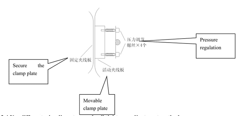
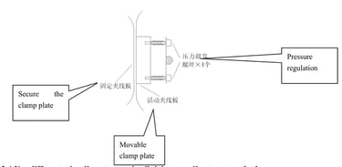
11.Before the winding process, adjust the pressure of the clamping plate. Adjust 4 pressure adjusting screws as shown in the following figure, pay attention to maintain 4 points of balance adjustment; The small side slide type and belt type winding machine adjust the elastic device on the clamp plate bracket, and finally pull the wire to be wound from back to front between the two clamp plates, there is a certain resistance and the wire will not accumulate in the clamp plate during the winding process.
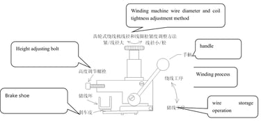
3.4 Use different wire diameters and coil tightness adjustment methods
1. The edge slide winding machine first pulls out the steel needle from the colloidal particles, and bends the steel needle upward when increasing the wire diameter or tightening the coil; When the wire diameter is reduced or the coil is loosened, the steel needle is bent to the rail arc close to the wire magazine; After the adjustment, insert it back into the colloid. Finally, the continuous wire and winding tightness in the winding process shall prevail.
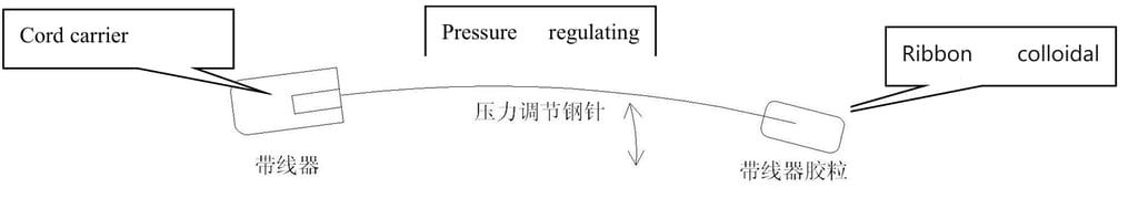
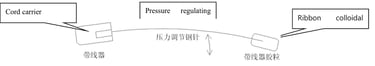
Note: There is no need to use colloids at the back of the belt of some small side slide winders, but the other operation methods are the same
2. Belt winding machine: Adjust the belt pressure at the back of the head, adjust clockwise to increase the pressure, suitable for winding thick wire diameter, counterclockwise to reduce the pressure, suitable for winding fine wire diameter, and finally take the continuous line and winding tightness in the winding process.
3. Gear type winding machine: adjust the wire ring pressure at the back of the head, and ultimately the continuous line and winding tightness in the winding process shall be appropriate.

4. Tape wrapping machine: Adjust the belt pressure knob above the head, adjust clockwise to increase the pressure, adjust counterclockwise to reduce the pressure, and ultimately, the continuous belt and tightness in the process of tape wrapping shall prevail.
3.5 Special operation of storage process and winding process of gear type medium speed winding machine
1. As shown in the figure of adjusting the wire diameter of the gear winding machine in 5.3 above, the handle of the wire ring pressure device needs to be pulled down when storing the wire; After the storage line is completed, it is pushed back to the original position, and the corresponding operation must be performed once each time the different processes are run.
2. The magazine of the gear type medium speed machine usually has a variety of depths such as 12mmand 16mm,when replacing the magazine of different depths, the installation height of the wire ring pressure should be appropriately adjusted (adjustment position as shown in 5.3 above), the general brake skin is 2-3mm from the magazine (the handle is kept in the position of the storage process).
3. If the installation is a movable metal cable holder and cable holder, the cable holder must be pulled out each time the wire is stored, and inserted back in place when winding the wire; To minimize the minimum finished inside diameter size of the equipment; Some models are installed with fixed metal tape or plastic tape (with wire hook), so this operation is not required.

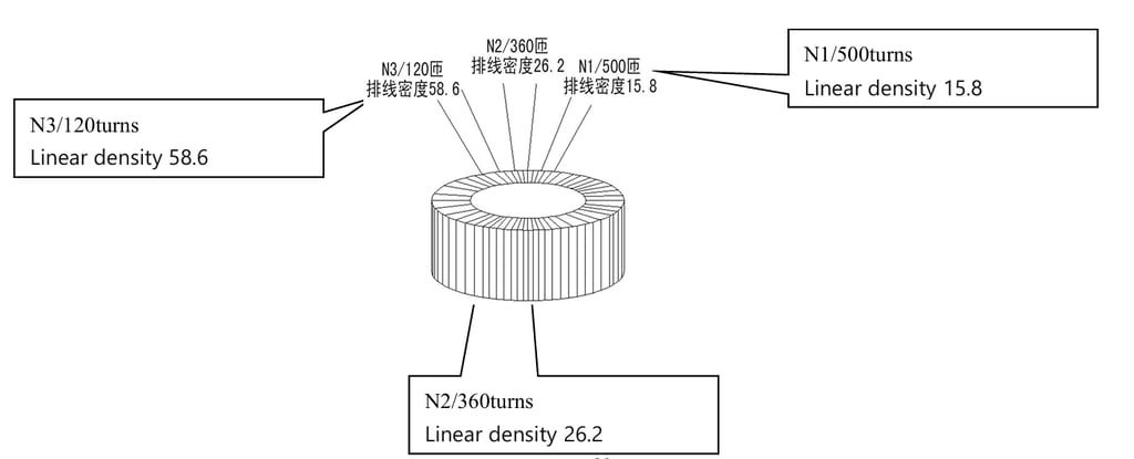
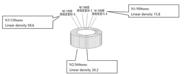
3.6 Method for adjusting wire spacing (density) of the coil on the iron core/magnetic toroid
1. Due to the shape and process characteristics of the ring coil, the shape size will change with the increase of the winding, the winding is usually not like square and other flat-wound coils, which are required to be layered evenly arranged according to the size of the wire diameter, but require a certain line distance (overlap) layered evenly arranged on the iron core/magnetic ring, so we use a more straight, simple and stable line distance adjustment method. When setting parameters, it is unnecessary to enter the inner diameter, outer diameter, height, wire diameter and other parameters of the iron core/magnetic ring to improve the use efficiency.
2. When resetting and winding a product specification or retrieving the original used product specification from the controller, the line spacing must be set first.
3. After setting parameters such as the number of wire storage/winding turns and process, start the device to complete the wire storage process first. After starting the wire winding process, adjust the wire spacing knob on the front panel of the machine.
4. Do not adjust the running speed knob of the machine panel during the winding process, otherwise it will affect the value of the line distance that has been set; If the product process needs to be adjusted, it is necessary to re-operate according to the above 7.2 method.
5. Because the model of the double frequency control system can not calculate the more accurate wire spacing value, the winding speed and wire spacing need to be adjusted immediately according to the actual winding effect. Note: Usually before adjusting the line distance, set the maximum running speed of the machine head.
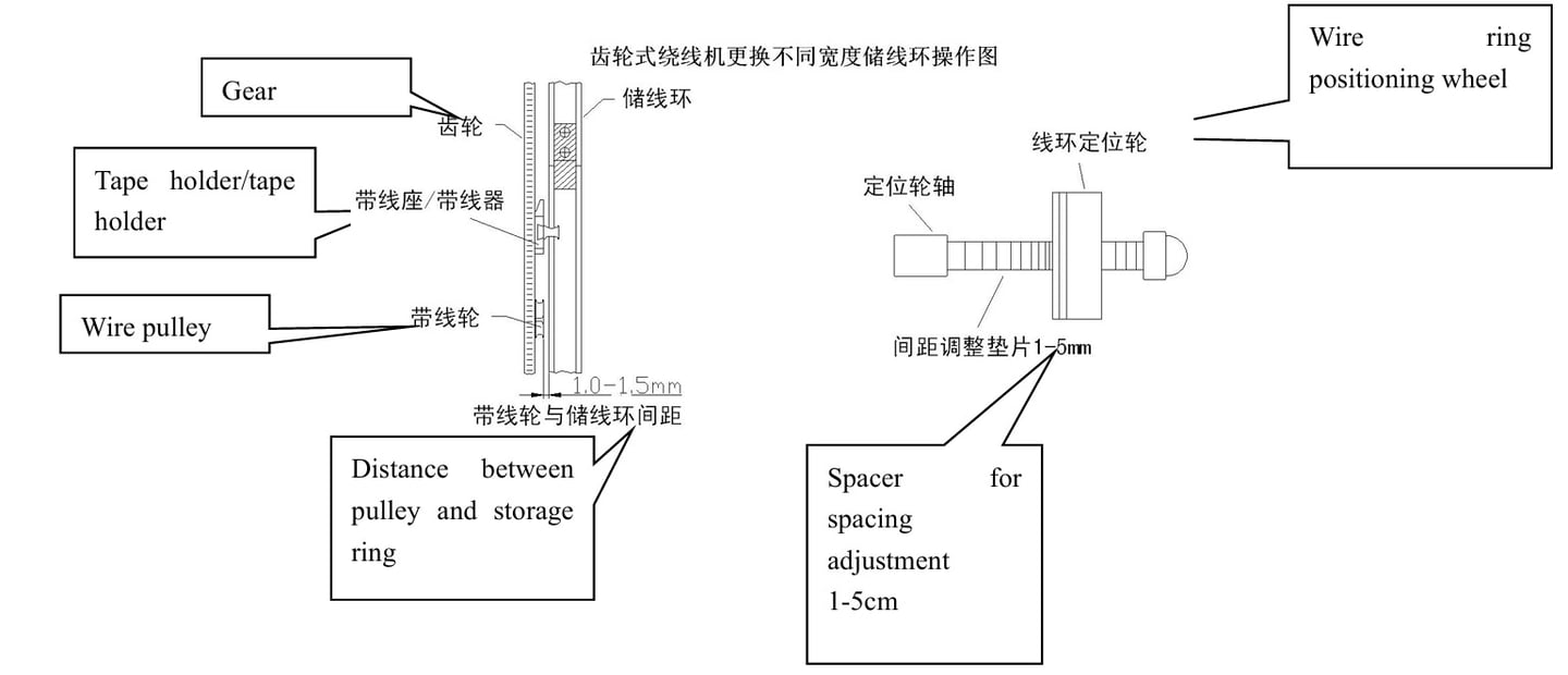
3.7 Gear type medium speed winding machine magazine replacement method
1. When it is necessary to replace the magazine of different widths, first remove the ring pressure, and then move all the positioning wheels of the wire ring evenly on the positioning wheel shaft. The installed magazine should be 1.0-1.5mm away from the belt wheel/belt seat.
2. If the longitudinal runout of the installed magazine is large, the positioning wheel shaft (except for the two other eccentric shafts near the gear) can be adjusted to the positioning wheel just contact the magazine, pay attention to not pressing, otherwise it is easy to break the wire when winding and affect the service life of the magazine; When the transverse runout is large, it is necessary to replace the new wire ring positioning wheel.
Chapter 4 Calculation of the number of stored turns of the winding machine and the number of stored turns of the tape wrapping machine
4.1 Calculation method for the number of turns stored in winding machine
Number of turns stored= (Total turns of winding x length of each turn of winding) / Perimeter of the storage loop
Length per turn = (outside diameter- inside diameter) + (height ×2)
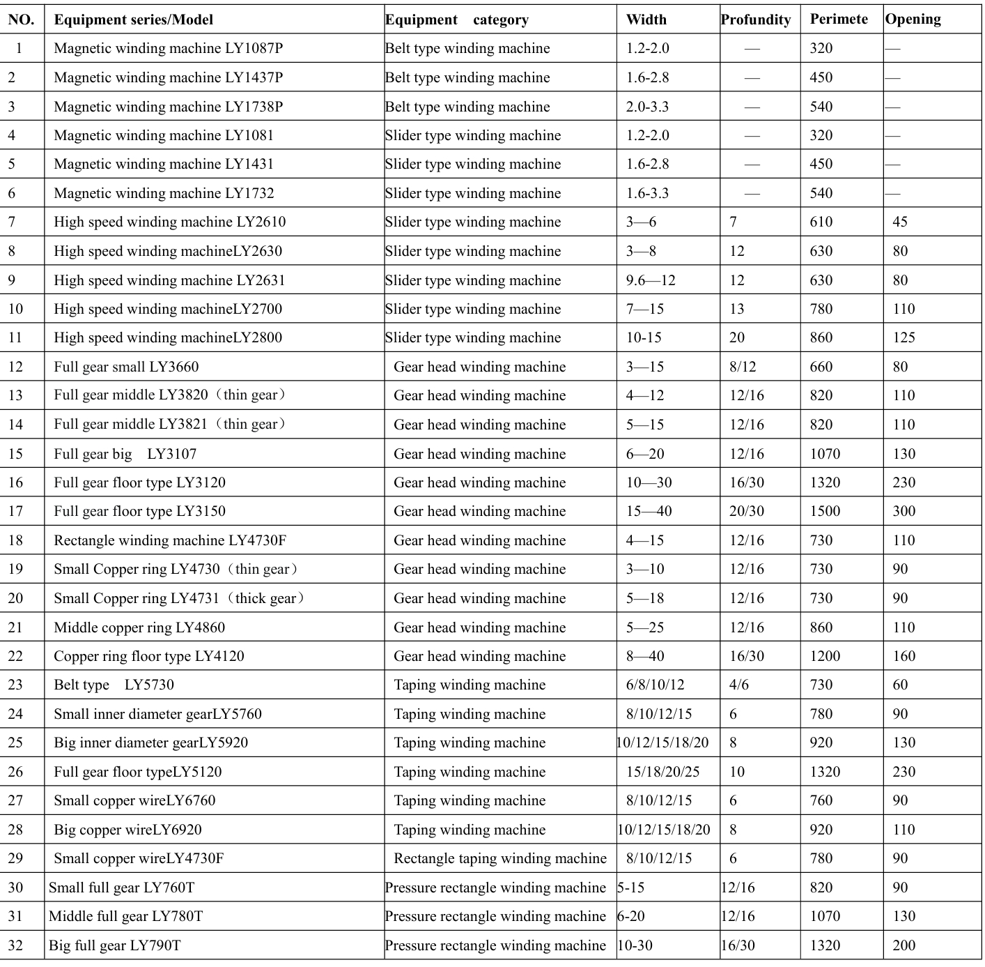
Ring circumference = ring diameter x 3.14 or refer to the table below
Note: When calculating the number of storage turns of the secondary, the length of each turn of the core after winding the primary winding should be calculated.
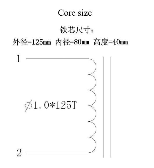
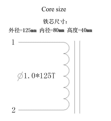
Example:The iron core size of the transformer is 90×50×40 mm (outer diameter-inner diameter height),the primary winding N1 is 860 turns, the secondary winding N2 is 230 turns,the circumference of the magazine is 730 mm,the calculation results of the primary storage turns are as follows:
N1= 860 * 120 / 730 =143匝
Total number of tape turns = Core outer circumference = core outer diameter x 3.14
Because the tape wrapping machine will also carry out the product package driving at the same time when storing the tape, the actual number of tape turns set on the controller should subtract the total number of tape turns from the number of tape storage turns. (If there is an error in actual use,you can enter the setting again to correct)
Number of belt turns =Total number of turns of tape * length of each turn of core / Girth of the tape ring
Length of iron core per turn = (outer diameter - inner diameter) + (height × 2)
Ring girth = Diameter x 3.14 or refer to the table below
4.3 Specification Table of main models and magazine/tapering(unit mm)
Chapter 5 Basic flow of device operation
1. Calculate the number of turns that need to be stored
2. Input the controller with the correct value according to the product parameter requirements of winding, such as the number of steps, the number of stored turns, the process, the number of winding turns, etc.
3. Place the whole roll of enameled cable under the cable routing support, pass the cable ends through the cable routing support, and clamp the cable ends tightly.
4. Open the gap of the wire magazine, put the iron core or the semi-finished product through the wire magazine and clamp between the three wire rubber wheels.
5. Reinstall the interface between the cable magazine and the gear, pull out the cable end from the cable support, and secure the cable magazine to the cable threading hole.
Note: Any model must ensure that the fixed wire tip is centered on the inside of the storage groove of the magazine.
6. The gear type winding machine needs to use a tool to push out the storage line drive piece on the wire ring and get stuck in the corresponding position of the wire seat. Some full-gear winding machines need to screw the storage line drive wheel to the transmission hole of the wire ring. (Refer to the above picture)
7. Press the Select key on the controller to select the step set to step 1 (usually step 01), and the automatic running light of the controller is kept off.
8. Press the start/stop switch on the operation panel of the machine (the start red indicator on the controller is on), slowly step down the pedal of the pedal governor, and start to store the cable.
9. After the wire storage is completed, the equipment will automatically stop. The full-gear winding machine will unscrew the wire storage drive wheel first (other models do not need to operate), hold the wire end by hand and cut it, and put the wire end on the wire conveyor or wire wheel according to the above figure.
10. Turn the magazine or gear (can be manually adjusted or press the point switch on the machine panel) to keep the wire end above the iron core.
11. Press the start/stop switch, slowly step down the pedal governor to start winding, to be wound 2-3 laps after the release of the wire, in the winding process need to pay attention to the state of the wire, to prevent involvement in the machine rotation structure or scratching phenomenon.
12. When winding is completed, the device automatically stops, open the magazine, and take out the product.
Chapter 6 Use of special functions
6.1 Winding or the number of turns, can not complete the storage line at one time, the need for multiple storage line and winding products
1. You can set any step as a storage process or a winding process.
Example: Product of specification 01
Step 01 is set to store wire
Step 02 is set to wind wire.
Step 03 can be set to store the wire
Step 04 can be set to wind the wire.
2. According to the above setting method, you can set the storage line 10 times and the winding line 10 times at most.
6.2 Fast Cable Storage function
1. Because the winding diameter is too thin or the product characteristics require low speed winding, the head speed can be set to be higher than the winding speed during the operation of the storage process to improve the operation efficiency of the equipment.
2.Setting method, adjust the process of the rear panel of the chassis 1 speed regulating potentiometer, you can change the highest line storage speed.
6.3 Multi-winding different line distance adjustment method
Winding multiple winding of different turns at the same time, but the position of the wire is required in the same direction, or each winding wire is connected to the end of the product
1. On the step setting page of the controller, set the cable spacing required by the corresponding winding step.
2. In the running state, adjust the controller rear panel of the cable distance 2/ cable distance
3 and cable distance 4 knobs, adjust the cable distance to a suitable value, a total of 4 lines can be preset, each line distance can be repeatedly set in any step. 3. When adjusting the specific line distance, you must first adjust the speed of the line distance 1, otherwise it will affect the value of the line distance of the following 3 segments. If only 3 segments of the line distance are used, it is recommended that the line distance 1 is not used during the setting.
4. After setting according to the above requirements, the device will automatically switch to the preset wire spacing of the winding when winding the corresponding winding.
5. When this function is not used, please set the line distance value to 1 on any step setting page, or adjust all 3 line distance potentiometers behind the controller to the maximum clockwise.
6. The above method can also be used because the winding wire diameter is large, the outer diameter of the winding process is larger products, such as a product specification for the outer diameter of 200mm, the wire diameter is 4.0mm, winding 200 turns, requiring two layers of each layer 100 turns 360 degrees evenly arranged, then the number of turns can be divided into two steps to complete, The corresponding step is set to the wiring distance 1 and the wiring distance 2, and adjust the knobs on the front panel of the machine and the wiring distance 2 knobs on the rear panel of the controller, respectively, so that the second layer of the wiring can be evenly arranged for a week or other required positions.
6.4 Intelligent operation function of tape wrapping machine
1. In the state of the coating machine, the equipment automatically runs at low speed under the tape storage step to avoid breaking the tape, and automatically accelerates to the fastest after the automatic cutting of the turn, which can be controlled without foot pedals, so that it is possible to operate two machines under the state of the core wrapping process, and improve the use efficiency of the equipment.
2. The tape storage speed and the tape wrapping speed after cutting can be adjusted by the process 1 speed knob on the back panel of the machine and the running speed knob on the front panel, respectively.
6.5 Method of using iron core automatic resetting wire in multi-layer winding
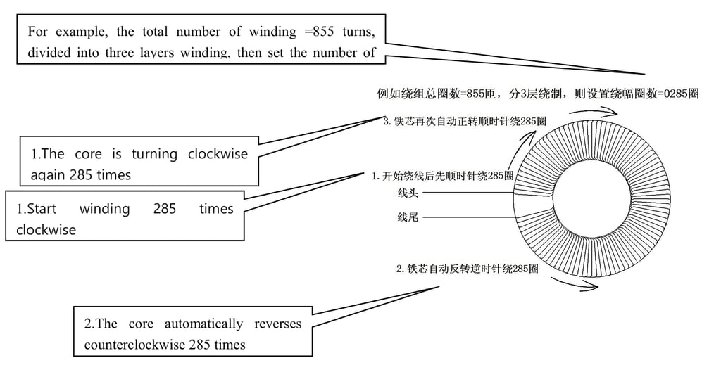
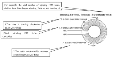
1. Set the controller as shown in the figure above. In addition, in Step 02 Setting, turn on the corresponding indicators of the winding, automatic wiring, and wiring direction buttons.
2. Change the indicator status of the wiring direction button to change the direction of the core during the initial winding. (For example, if the light is on, clockwise rotation starts, if the light is off, counterclockwise rotation starts)
3. Reasonable use of this function can realize the entire winding multi-layer winding, reserve a certain Angle at the junction of each layer without winding, and there will be no bulge phenomenon after connecting the lead, improving the appearance of the product; There is also an automatic reversal of the iron core whenever it is wound to the joint of each layer, which can improve production efficiency without stopping the line head.
Chapter 7Automatic wiring system winding machine controller use method
The winding machine installed with this control system has the function of automatically adjusting the line spacing, which does not need to be controlled by adjusting the iron core speed like the traditional model
7.1 Controller Operation Panel and Standby Screen

7.2 Usage of Key Functions
1. Setting Entering the data editing state, press the setting key repeatedly to jump directly to the next setting page, (operation is invalid in the running state)
2.Select Select the step to run in standby. Invalid operation in running state
3. Storage/winding With an indicator light, the operation is effective when entering the step setting page of the setting state. When it is set to the storage or winding process, the corresponding left and right indicators are lit. (This operation is valid on the step Settings page)
4.Automatic start With an indicator, this step is automatically started when the previous step is completed. The operation is effective when the current step setting page is lit. For example, when the step setting page is lit, step 02 laps will automatically start step 03 after the completion of the run.
5. Automatic wiring with indicator light, when the light is on, the core steering is automatically controlled (the direction of the core wiring rotation is determined by article 6 below when the step is started for the first time), when the light is not on, the direction of the wiring is controlled by the toggles switch on the panel (the operation is effective in the step setting page, each step can set the automatic wiring or manual wiring direction separately).
6. Spread direction. With an indicator, the operation is effective in the setting state. When the iron core rotates clockwise when it is on, it starts counterclockwise when it is off. The operation is effective when each step is set on the page (the operation is effective when each step is set on the page).
7. Start/stop It has an indicator. When it is on, it is in the running state. When it is off, it is in the standby state. (Set the value 7 input function in the state)
8. Automatic operation with indicator light, when it is on, it will run directly after pressing the start key, when it is not on, it will run with external pedal speed regulation, (Set the value 8 input function)
9. Numberof laps modification In the suspended state after running, operate once, the number of completed laps flashes, press the arrow key to add or subtract the number of completed laps displayed; Press the turn number change key again to save and exit. (Set the value 9 input function in the state)
10. Output clearance 1, output is reduced by 1; Press and hold for 2 seconds to clear the finished output. (The operation is invalid in the Settings state)
11.Left and right arrow In the setting state, select the item to be edited, and press the key for each parameter set (that is, press the key for setting the state and save the setting function at the same time); Save the preset parameters and automatically skip to the next parameter to be set, press Key returns to the previous parameter value; In the standby state, use the turn number change key to set the turn number addition or subtraction function.
12.COPY/output In the setting state, it is the COPY function. Press the copy key to copy all parameter Settings of the previous step. In the standby state, it is the output function key, press the output key for 2 seconds, the output value flashes, then press the number key to enter the output value, and then long press the output key for 2 seconds to save (operation is invalid in the running and setting state), tap once to convert the output setting value displayed in the standby state, and automatically change back to the completed output value after release.
13. Clear/save in the standby and running state, touch once to clear the completed circle value; In the setting data state, save parameters and return to the standby state function key, return to the standby state of Step 01 page.
14. Digit key 0-9 Enter the preset parameter value in the Setting state. In the standby or running state, it is the corresponding function key indicated above.
15. When setting the two non-numerical items, the winding mode and the wiring mode, press the key to switch the setting.
7.3 Controller Standby page and Setting page
7.4. Parameter setting range and function definition (CNC17-06 Automatic wiring control system type)
1. Specifications: 01-50 (50 product specifications can be set separately).
2. End step: 01-20 Set the total number of work steps that need to be run.
3. Outer Diameter Inner diameter height: 000-999 Display the corresponding size of the input core/magnetic ring (unit mm)
4. Numberof slow laps: 00-20 Set the number of laps to complete the last slow run. (Eliminate the number of turns error caused by the inertia of mechanical operation, usually set to 02-05 can be)
5. Slow speed: 000-100 Set automatic operation, slow running speed (percentage) after the number of slow laps.
6. Winding mode: wire diameter/number of layers set the arrangement of the coil on the iron core. When set to wire diameter, the iron core moves anAngle according to the size of the preset wire diameter each time it is wound; When set to the number of layers, the rotation Angle of the iron core is automatically distributed evenly according to the preset number of layers/turns and the winding Angle.
7. Step: 01-20 This item cannot be set, and the step number of the current page is displayed (a maximum of 20 working step parameters can be set/saved under each specification). 8. Numberof turns: 0000-9999 Sets the preset number of turns for the current step.
9. Speed: 001-100 Set the running speed (%) of the current step. This setting is invalid when the pedal speed is used.
10. Calculate the number of turns: 0000-9999 display the storage coil value automatically calculated by the system.
11. Wire diameter: 0.00-9.99 Set wire diameter value (unit mm)
12. Winding Angle 000-720: Set the circle value when the core turns to automatic reversal in automatic wiring mode. (After setting the value, it also needs to be used with the automatic wiring function key on the keyboard)
13. Output: 0000-9999 shows the number of processed products, when the preset output is completed, the buzzer alarms and prohibits starting again; When the output is set to 0000, the output is not restricted.
14. Number of completed laps: 0000-9999 Displays the number of completed laps in the current step.
15. Acceleration time: 0.1-9.9 Set the running time head running acceleration time; . 0-5 seconds, usually set to 1.0.
16. Click speed: 000-100 Set the speed when pressing the core click button,
17. Wire speed: 000-100 Set the speed of synchronous rotation of the wire wheel in the winding state.
18. Ribbon: 1-6 represents the order displayed on the screen, and all specifications perform one ribbon.
1). Spindle operation mode: the winding machine is set to 1 or 3 tape wrapping machine is set to 2/ or 4
2). Tape cutting machine action time: 0.5-5 seconds, setting range 0-9. 0=0.5 seconds, 1=1 second, 9=5 seconds.
3). Automatic start interval: 0 indicates no interval, 1=1, 2=1.5, 3=2, 4=2.5, 5=3, 6=3.5, 7=4, 8=4.5, 9=5 seconds.
4). Turn number sensor display ratio :1 =1:1, 2=2:1, 3=3:1, 4= 4:15 = 5:16 = 6:17 = 7:18 = 8:19 = 9:10 =10:1.
5). The effective number of sensors: when set to 1, all processes use 1 sensor port, when set to 2, two sensor ports are used, and one sensor for each storage process and winding process.
6). Applicable models: 1 for winding machine 2 for wrapping machine. The winding machine is usually set to 100111, and the wrapping machine is usually set to 200112
19. Positioning mode: 1-2 is set to open the windingAngle function, the core positioning to the winding Angle, set to 1 is to turn to the windingAngle after starting, and then directly run the winding; If it is set to 2, press to turn to the winding Angle after starting, and press again to run the winding after starting.
20. Wiring mode: Outside diameter- Inside diameter setting When the winding mode is wire diameter mode, the size of the iron core rotation is relative to outside diameter or relative to inside diameter. (Usually set to the inside diameter, because if set to the outside diameter, because the size difference between the inside and the outside diameter of the iron core is large, it will lead to serious problems of the inside diameter overlap)
21. Rubber wheel diameter: 000.0-999.9 Set the diameter of the rubber wheel actually installed on the current model (iron core clamp wheel, actual measurement shall prevail), the wrong value setting may lead to inaccurate wiring accuracy; If you need to replace different rubber wheels, you need to change the parameter Settings simultaneously.
22. Diameter of wire magazine: 000-999 Set the diameter of the wire magazine installed on the current model (to ensure that the number of coils is accurate, it is necessary to enter the average diameter of the effective wire storage slot, not the maximum diameter; If 300mm outer diameter storage wire ring, input about 285mm); The purpose of this parameter is for the controller to automatically calculate the value of the storage coil.
23. Motor end gear: 00-99 Set the number of teeth of the transmission gear that drives the motor to be installed. The factory default setting is 10.
24. The number of teeth at the end of the wire row: 000-999 sets the number of gears and teeth installed on the drive shaft at the end of the rubber wheel of the wire row, and the factory default setting is 040.
Tip: Sometimes the device can not start suddenly, that is, after pressing the start key, the controller will emit a drop alarm sound; This is because the preset output value of the controller has been completed and needs to be cleared to complete the output value or set to 0000.
Operation method:
1. Press and hold the controller digit 0 key for 2 seconds to clear the finished output value.
2. Press and hold the output key for 2 seconds until the output value blinks, enter 0000 and press and hold the output key for 2 seconds until the output value does not blink.
Common operations are as follows:
1. When the device is in standby state, press the select key to switch to the current step.
2. In standby or running state, you can press the reset/return key to clear the completion circle value.
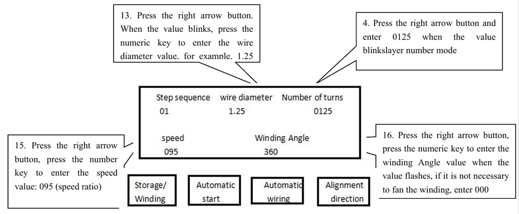
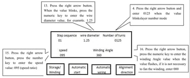
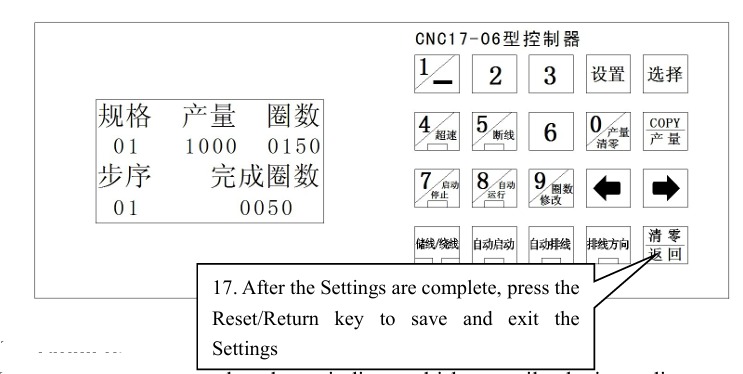
7.5 Setting example flow chart (CNC17-06 automatic wiring control system type)
(Example: Setting method of parameter winding in the following figure)
7.5.1 Process for Setting Parameters When the Winding Mode is Layer Mode
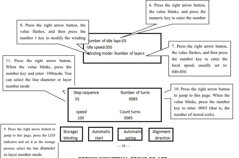
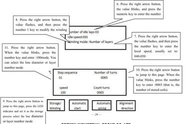
Note: The calculation of the number of turns needs to be automatically calculated according to the winding value set at the back, so usually skip the setting of step 01 first, after setting the winding step at the back, and then return to the calculation value displayed on this page to enter the number of stored coils.
Operation tips:
In the wire diameter mode, when winding multi-layer coils, the inner diameter of the product will become smaller because of the increase of the number of winding layers, and the problem of winding more than 2 layers will appear. In this case, you can press the controller The left and right arrow keys increase the temporary wire diameter value by 0.1mm per press; When a product is rewound, the controller automatically returns to the wire diameter value of the first layer.
7.5.2 Parameter Setting Process When the Winding Mode is Layer Mode
Note:All steps are the same as 7.5.1, just change the wire diameter in step 8
Note:The calculation of the number of turns needs to be automatically calculated according to the winding value set at the back, so usually skip the setting of step 01 first, after setting the winding step at the back, and then return to the calculation value displayed on this page to enter the number of stored coils.
Note:
1. When setting the storage coil value, you can skip the step setting page first, because the new controller has the function of automatically calculating the number of storage coils, the premise is that you need to set the following winding step coil value, and then return to the storage wire step page, the value below the calculation of the number of coils is the automatic calculation of the number of storage coils, and then refer to the value of the manual input to the number of turns. (The calculated value will cause errors due to the different number of winding coils and lead length, you can try to wind one and then enter the setting state to correct it)
2. Layer mode setting skills: Because the movement of the core driven by the rubber wheel is driven by mutual surface friction when winding, there will be slight slip phenomenon, or the actual winding, the product lead position is not winding, and it needs to be moved over; Therefore, when we set, we can increase or decrease the value of the winding Angle appropriately, such as setting 370 degrees, and then look at the actual wiring effect after winding a product and enter the setting state to correct the winding Angle setting value.
3. When installing the control system, if the core clamp wheel (wire pulley) with different diameters is replaced, the diameter setting value of the controller rubber wheel must be modified accordingly (Chapter 7 7.4-21) to ensure that the wire Angle is accurate.
Chapter 8 Maintenance
1. Add lubricating oil to the gear and other rotating parts on the equipment when in use. Copper ring type medium speed winding machine series can not add solid butter, otherwise it will affect the performance and service life of the equipment.
2. In order to maintain good running characteristics for a long time, please often remove the wire, film and other debris on the machine, especially the debris of the rotating parts.
3. Check the drive belt and parts screws regularly for loosening.
4. Check frequently whether the wearing parts of the equipment such as wire carrier, transmission belt, magazine, bearing are worn.
5. Periodically check whether the input power supply is in poor contact and whether there is enough power on the power supply side.
6. When the magazine is worn for a certain period of time, please repair or replace it in time, otherwise it will affect the service life of other accessories.
Chapter 9 Common Trouble shooting
1. After starting the machine head does not turn, the running speed is displayed 0.00 and blinks, pressing the two machine head switch is effective; (1) Replace the 25pin data cable of the controller. (2) Check and replace the head speed regulating potentiometer. (3) Replace the controller.
2. Start the rear cable does not turn, and the cable distance displays 0.00 or other three digits and blinked: (1) Replace the cable density potentiometer or the cable direction switch; (2) Replace the controller 25pin data cable; (3) Replace the controller.
3. The indicator light on the start controller is not on, and the machine head and the wiring device are not running; Press the start/stop button on the controller to start: (1) Replace the square red start/stop switch on the front panel; (2) Replace the controller 25pin data cable.
4. All equipment is normal, but the number of turns is not counted during operation; (1) Adjust the distance of the number of turns sensor; (2) Replace the number of turns sensor or controller. (3) Confirm whether the model of the sensor is correct and normal PNP normally open type.
5. The tape wrapping machine operates normally, but will not automatically cut the tape: (1) Replace the electromagnet on the bracket; (2) Replace the controller.
6. All functions of the equipment operation panel are normal, but the head and the wiring device do not operate after starting; Replace the pedal governor or controller and the controller 25-core data cable.
7. There is no display in the running speed display window: check whether the power supply is in bad contact or replace the head inverter.
8. There is no display in the line density display window: check whether the power supply is in bad contact or replace the line inverter.
9. The running speed and line distance display window and controller display have no display:
(1) Check whether the power is plugged in.
(2) Check or replace the power switch, (3) check whether the current fuse is burned out.
10 During the use of the tape machine, it is easy to bulge out the film and break the tape from the inner ring of the tape ring:
(1) Check whether the number of tape magazines is too much, most models should be controlled within 20 rings for the best effect,
(2) drop a small amount of oil on the elastic adjusting belt of the tape.
11. The wire is often broken during the winding process: check whether the side slide is too tight, and whether the pressure on the wire ring of the medium speed machine is too large.
12. When the equipment is running, it is suddenly stuck or noisy: check whether there is a film or enamelled wire stuck into the gear change.
13. The winding patent leather is damaged during the winding process:
(1) check whether the belt and belt wheel are worn too much,
(2) check whether the magazine is worn or the gap at the opening is too large,
(3) check whether the top of the head over the wire bracket is damaged,
(4) observe whether the product is too small, and the gear ring or magazine scratches.
Chapter 10 Wiring diagram of main electrical components of the equipment
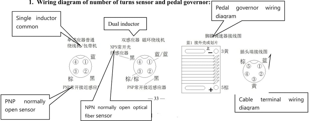
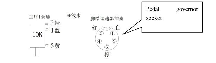
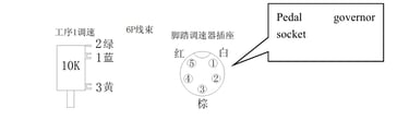
1. Wiring diagram of number of turns sensor and pedal governor:
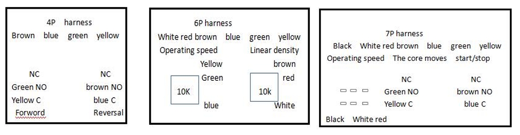
2. Chassis panel control switch wiring position diagram: (Pay attention to whether the installed switch C, NC, NOpin is correctly arranged)

3. Frequency converter wiring diagram: (The head and the wiring of the two frequency converters are consistent)
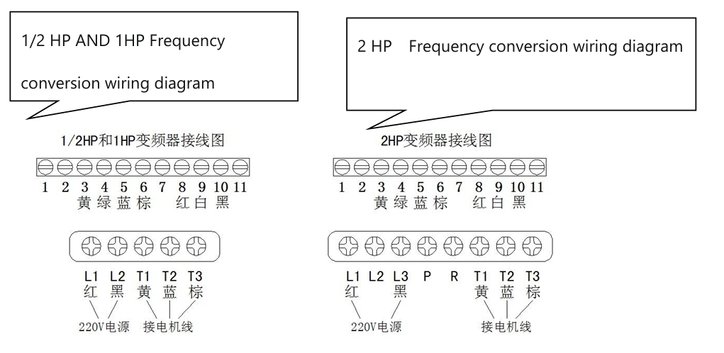
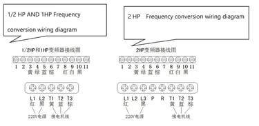
Note: If the connection method is the same as the above figure, but the direction of the equipment is opposite to the corresponding process, the wiring position of the T2/T3 terminal motor line can be changed
4.Rear panel wiring diagram:
Quality
Leading manufacturer of toroidal winding machines in China.
Innovation
Reliability
+8613151099556
© 2025. All rights reserved.